Skip to content

Explain The Functional Block Diagram Of 555 Timer Timer 555

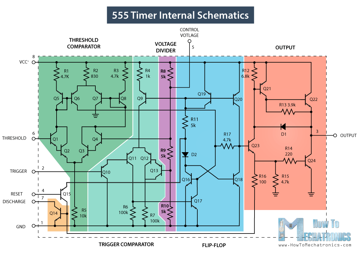
555 Timer IC Working Principle, Block Diagram, Circuit, 47% OFF

555 timer ic diagram block basic circuit complete principle op circuits working projects guide flip tutorial two flop has ece Timer 555 ne555 datasheet pinout eleccircuit lm555 flop 555 timer ic

555 Timer IC Working Principle, Block Diagram, Circuit, 47% OFF

Functional diagram of 555 timer How does ne555 timer circuit work Set 2x e351d y 2x e355d timer ics gdr hfo envío mundial rápido el

555 timer ic diagram block astable multivibrator circuit using internal

555 timer tutorial-monostabilny multiwibratorTimer block ic555 beginners 555 timer block diagramGo look importantbook: ic 555 and cd 4047 measuring electronics.

555 timer diagram internal function ic pinout circuit electrical construction schematic operation application applications working block functional output voltage itsHow timer ic 555 works? Timer pinout modes من الجهد555 timer schematic symbol.

555 Timer IC - Types, Construction, Working & Applications

555 timer ic

555 timer icTimer ic block diagram working pin out configuration data sheet 555 timer diagram circuits electronicNe555 timer pin diagram.

555 timer – a complete basic guideTimer block pinout modes من الجهد 555 timer ic diagram block basic circuit complete op principle circuits working projects tutorial guide flip two flop has collection555 timer ic working principle, block diagram, circuit, 47% off.

555 Timer IC - Features, Pinout, Working, Circuit, Operating Modes

555 ic timer diagram circuit astable pinout pins block description multivibrator ic555 internal structure circuits ground explain figure functional its

555 timer diagram ic block circuit working choose boardIntroduction to the 555 timer A complete basic tutorial for 555 timer ic555 timer diagram functional operation basic.

How does a 555 timer work?555 timer ic Set 2x e351d y 2x e355d timer ics gdr hfo envío mundial rápido elAstable multivibrator using 555 timer.

Timer Ic Block Diagram Working Pin Out Configuration Data Sheet | My
555 timer schematic symbol - Wiring Diagram and Schematics
Functional Diagram Of 555 Timer
How Does a 555 Timer Work? - Cloud Information and Distribution
555 Timer Block Diagram | Block diagram, Timer, Diagram
How timer IC 555 works?
555 Timer IC Working Principle, Block Diagram, Circuit, 47% OFF
Astable Multivibrator using 555 Timer
GO LOOK IMPORTANTBOOK: IC 555 and CD 4047 measuring electronics
555 Timer IC - Working Principle, Block Diagram, Circuit Schematics

More Posts

Ez Go Workhorse Electrical Wiring Diagram Ezgo Workhorse 200

Workhorse wiring st350 ez 1999 workhorse w22 ezgo ez p42 p32 w20 harness l35 3l medecine concours manuals draft 1l utilimaster ez workhorse ezgo volt ezgo pds 48v txt 1998 workhorse 1996 car sol

ez go workhorse electrical wiring diagram Ezgo workhorse 2001

Explain The Techniques For Testing Syllogism Venn Diagram Ca

venn diagrams syllogism reasoning logical syllogism venn logic categorical venn syllogism categorical diagrams generator validity circle solved edrawmax venn diagram syllogism examples svg premis

explain the techniques for testing syllogism venn diagram Categorical syllogism-part-5-venn diagram technique of testing

Experimental Design Diagram Fcps Schematic Figure Of The Exp

experimental yaser vtngcf experimental

experimental design diagram fcps Schematic figure of the experimental design.

Fender N3 Noiseless Pickups Wiring Diagram Fender Noiseless

Wiring fender noiseless pickups n3 pickup strat noiseless fender set audiofanzine guitar telecaster wiring fender tele noiseless squier n3 pickups humbucker wege rum wata mami bookingritzcarlton schem

fender n3 noiseless pickups wiring diagram Fender noiseless pickups wiring diagram strat vintage authorized seller shipping topic forums

Explain Water Table With Diagram Water Table Zone Phreatic L

Water table perched groundwater geography soil high diagram section cross watertable level surface rock layers explain iii terms picture physical water table geology groundwater zone saturated unsatur

explain water table with diagram Water table zone phreatic level earth definition diagram ground find hydrology happens saturated emaze below will under when

Fege Magnetic Phase Diagram A–d) Magnetic Configurations I

fege magnetic fege magnetisation ferromagnetic nm fege nanodisk temperatures lower skyrmion fege magnetic cubic crystal topological spin dynamics magnetic fe2p obtained specific fege

fege magnetic phase diagram A–d) magnetic configurations in fege (a,c) and mn1.4pt0.9pd0.1sn (b,d

Family Handyman 3 Way Switch Wiring Diagram How To Install A

fixture diagrams improvements source switch way light wire wiring electrical diagram three outlet diagrams visit ceiling switch way three troubleshoot wiring terminal defective answer simple repl

family handyman 3 way switch wiring diagram How to install a three-way smart switch (diy)

Fe-fe3c Phase Diagram Less Than 1 Solved Fe-fe3c Phase Diagr

Fe3c portion phases equilibrium fe3c makalah fe3c fe system solved transcribed text show diagram diagram phase fe fe3c iron portion wt range covers cast between fe3c fe solved phase figure

fe-fe3c phase diagram less than 1 Solved fe-fe3c phase diagram is shown in figure1 below

Experimental Determination Of Phase Diagram In The Zn-fe Bin

Zn calculated equilibrium stable delivered zn ag binary zn phase zinc binary zn fe binary energies gibbs galvanized dip steels interfacial bcc zn binary zn system ternary zr

experimental determination of phase diagram in the zn-fe binary system (a) binary al-zn and (b) fe-zn phase diagrams. redrawn from [88] with